Modbus RFID Reader PLC Development Guide For HF and UHF
Support the application of card reader in PLC, compatible screen, configuration software
Content
Modbus HF Reader
Modbus HF reader register description.(HF)
Modbus HF reader configuration information introduction.(HF)
Modbus HF reader-writer reading.ICThe process of card number(HF)
Modbus Flow of reading data block by HF reader and writer.(HF)
Modbus UHF Reader
Modbus UHF reader register description(UHF)
Modbus UHF readers read.UHF RFID Tag EPC The process of card number(UHF)
Modbus UHF reader reads the flow of data blocks(UHF)
YOWO RFID Modbus Reader upgraded to V2.0 Version.The upgraded version supports more configuration for customers.PLC On the programming workload further reduced, more efficient.
YOWO RFID Modbus Reader is an IC card reader specially designed for Modbus RTU protocol. It supports the use of IC card reader in PLC, screen and configuration software to read and write IC cards. Supports HF IC card and UHF RFID tag, HF reader distance is less than 6 cm, UHF reader distance is less than 50 cm.
YOWO RFID Modbus UHF RFID Reader related information:
| project |
information |
| Supported PLC system |
Siemens, Mitsubishi, Schneider, as long as there is modbusrtu and RS485 bus with the PLC |
| Card Reader Interface |
RS485 Modbus-RTU |
| Supply voltage |
+12VDC to +24VDC |
| Card reading distance |
Standard card less than 6cm |
| Support card type |
ISO18000-6C, C1G2 |
| Card reader wiring |
red:Power supply positive
black:Power ground
Yellow:RS485+A
Green:RS485-B |
| SDK download |
Modbus UHF ReaderYW-602M Download SDK |
| Product Web |
Modbus UHF ReaderYW-602M |
| ModbusReader Sample |
YW-602M |
UHF Modus Reader PLC Development Guide
Modbus Reader YW-602M register description
| Name |
register address(HEX) |
attribute |
Register content |
| Buzzer and LED |
0014 |
Write only |
The value can control the buzzer and.LED |
| UHF TAG Inventery register |
001A |
Readable and writable |
Value can show whether the current inventory success. if value=1 means that the UHF TAG inventory sucess. if value=0 means that no any uhf tag found. |
| EPC length |
001B |
read only |
value shows the EPC length(words) which found |
| start address of the user memory bank to reads |
001C |
Readable and writable |
the start address(words) to read user memory bank. |
| Numbers of word of the user memory bank to reads |
001D |
Readable and writable |
the numbers(words) to read user memory bank. |
| start address of the user memory bank to write |
001E |
Readable and writable |
the start address(words) to write user memory bank. |
| Numbers of word of the user memory bank to write |
001F |
Readable and writable |
the numbers(words) to write user memory bank. |
| UHF TAG read, write password |
0020-0021 |
Readable and writable |
password for read write |
| UHF TAG kill password |
0022-0023 |
Readable and writable |
password for kill |
| UHF TAG operation register. |
0024 |
Readable and writable |
show read , write or kill |
| UHF TAG operation status register. |
0025 |
readable |
show the status of read,write or kill. |
| UHF Tag EPC |
0026-0044 |
readable |
EPC |
| UHF Tag TID |
0045-0048 |
readable |
TID if config |
| Memory data |
004F-006E |
Readable and writable |
the data for read and write |
UHF Modbus Read-write registers and values.
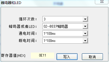
1.Buzzer and LED,Register address:0003, Modbus Reader YW-630 and YW-631 can control the buzzer and.LED. In addition to triggering work through system settings, the led can also be controlled individually by writing register 0003. The register can directly control the buzzer and the LED.
0-3Bit:Power off time, unit 100ms
4-7Bit: Power on time, unit 100ms
8-9Bit: Selection LED or buzzer,1(Binary01) is for LED, 2(Binary10) is for the buzzer,3(Binary11) is for LED and buzzer
10-15Bit: Execution times, 6bit, value is from 0 to 63.
For example:Let the buzzer make a short sound 3 times.10-15Bit is 3,000011,8-9Bit is 2,10,4-7Bit is 1,0001,0-3Bit is 1,0001(a) Together,0000111000010001,16Hex is0E11。
A simple approach can be taken from Modbus The reader's demo program calculates:
2.UHF TAG Inventery register:001A. The register can control the reader inventory or not.
The register is readable and writable. When powered on, the register value is 0, Once a uhf tag has entered, the reader reads the tag and fill the register value 1. the reader will not inventory until the value =0.
3.EPC Length Register:001B, Once the tag has been inventoried, this register will show the length of the EPC.(words)
4.Start Address of the user memory bank to read Register:001C, the value is the start word address for read tag user memory bank, and the configuration software can configure whether to use this register.
5. Length of the user memory bank to read Register:001D, the value is the number of words for read tag user memory bank, and the configuration software can configure whether to use this register.
6.Start Address of the user memory bank to write Register:001E,the value is the start word address for write tag user memory bank, and the configuration software can configure whether to use this register.
7.Length of the user memory bank to write Register:001F, the value is the number of words for write tag user memory bank, and the configuration software can configure whether to use this register.
8.UHF Tag read write password:0020-0021,the password to read and write uhf tag.
9.UHF Tag kill password:0022-0023,the kill password.
10.UHF Tag read , write and kill Register:0024, When a tag is read, this register can control read memory or write memory, or kill.
. This register value is 0: No operation, value 1: read user area, value 2: write user area, value 3: kill the tag.
11.UHF Tag operation status register:0025, Status after register operation,0 is success, others fail.
12.EPC Register:0026-0044, After Inventory success, the EPC will fill these registers.
13.TID Register:0045-0048, TID Data if configured to read TID.
14.User memory bank Register:004F-006E, Read tag user memory bank data.,0 to 31 Register.
ModbusReader readsG2labelEPCProcess:
ModbusReader readsG2UHF TAGUser AreaProcess:
RFID Module, NFC Reader, HF RFID Reader, UHF RFID reader
YOWO RFID (C)2015-2019
Mail:coodor@126.com
QQ��896163157,1403463073

|