Modbus RFID Reader PLC Development Guide For HF and UHF
Supporting the application of card reader in PLC, compatible screen, configuration software
Content
Modbus HF Reader
Modbus HF reader register description.(HF)
Modbus HF reader configuration information introduction.(HF)
Modbus HF reader-writer reading ICThe process of card number(HF)
Modbus Flow of reading data block by HF reader and writer.(HF)
Modbus UHF Reader
Modbus UHF reader register description(UHF)
Modbus UHF readers read.UHF RFID Tag EPC The process of card number(UHF)
Modbus UHF reader reads the flow of data blocks.(UHF)
YOWO RFID Modbus Reader upgraded to V2.0 Version.The upgraded version supports more configuration for customers.PLC On the programming workload further reduced, more efficient.
YOWO RFID Modbus Reader is an IC card reader specially designed for Modbus RTU protocol. It supports the use of IC card reader in PLC, screen and configuration software to read and write IC cards. Supports HF IC card and UHF RFID tag, HF reader distance is less than 6 cm, UHF reader distance is less than 50 cm.
YOWO RFID Modbus HF reader related information:
| project |
YW-630MA |
YW-631MA |
YW-630NA |
YW-635MK |
YW-602M |
| Supported PLC system |
Siemens, Mitsubishi, Schneider, as long as there is.modbusrtu and RS485 bus with the PLC |
| Card Reader Interface |
RS485 Modbus-RTU |
Ethernet Modbus TCP |
RS485 Modbus-RTU |
RS485 Modbus-RTU |
| Bus Isolated |
false |
true |
|
true |
false |
| Supply voltage |
+12VDC to +24VDC |
| Card reading distance |
less than 6cm for standard size card |
10cm for standard size card |
60cm for standard size card |
| Support card type |
M1,S50 and its compatible cards |
EM4001,TK4100 |
UHF Gen2 rfid tag |
| Card reader wiring |
red:Power supply positive
black:Power ground
Yellow:RS485+ A
Green:RS485- B |
red:Power supply positive
black:Power ground
RJ45: Net |
red:Power supply positive
black:Power ground
Yellow:RS485+ A
Green:RS485- B |
red:Power supply positive
black:Power ground
Yellow:RS485+ A
Green:RS485- B |
| SDK download |
Modbus ReaderYW-630,YW-631Download SDK |
YW-635MK |
|
| Buy ModbusReader Samples |
YW-630MA |
YW-631MA |
YW-630NA |
YW-635MK |
|
Modus Reader PLC Development Guide
Modbus Read-writer register description.
| Name |
Register address |
Attribute |
Register Contents |
| Buzzer and LED control |
0003 |
Write Only |
The value can control the buzzer and.LED |
| Card Serial Number |
0004 to 0007 |
Readable and writable |
Value is the card number while it is not 0, if card serial number is 4 bytes. it will fill 0004 and 0005. |
| Card operation |
0008 |
Write Only |
1 For reading block, 2 For writing, 3 Halt, 4 initialize value, 5 Get the balance for the value, 6 Decrease value , 7 Increase value |
| Card operation status |
0009 |
Read-only |
0 For operation success, other failure. |
| Card operates the corresponding block. |
000A |
Readable and writable |
High bytes for the number of blocks, low bytes for the number of blocks, not across the sector. |
| The operation of the block authentication key. |
000B to 000D |
Write Only |
Key is 6 byte, occupation 3 registers |
| Block data |
0010 to 002F |
Readable and writable |
32 registers filled 64Bytes, corresponding to the most cards 4 block, the register used corresponds to the card operation.(Register:000A)Related |
Modbus Reader registers and register values.
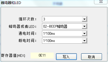
1.Buzzer and LED,Register address:0003, Modbus Reader YW-630 and YW-631 can control the buzzer and.LED. In addition to triggering work through system settings, the led can also be controlled individually by writing register 0003. The register can directly control the buzzer and the LED.
0-3Bit:Power off time, unit 100ms
4-7Bit: Power on time, unit 100ms
8-9Bit: Selection LED or buzzer,1(Binary01) is for LED, 2(Binary10) is for the buzzer,3(Binary11) is for LED and buzzer
10-15Bit: Execution times, 6bit, value is from 0 to 63.
For example:Let the buzzer make a short sound 3 times.10-15Bit is 3,000011,8-9Bit is 2,10,4-7Bit is 1,0001,0-3Bit is 1,0001(a) Together,0000111000010001,16Hex is0E11。
A simple approach can be taken from Modbus The reader's demo program calculates:
2.Card Serial Number(Card No.)register,Register address:0004-0007, Modbus Reader YW-630 and YW-631 support 4 Bytes card serial number, can also supported 7Bytes card number, currently mostly 4Bytes card number. 4Bytes will fill 0004 and 0005 Registers.
The register can be readable and writable. When powered on, the register is 0 for card request status, once a card has requested, the card reader reads the card and immediately fills the register and no longer request the card.Until the program clears the register, that is, write the register 0004 and 0005 register=0, Once set to 0 After the card reader starts the card search process until after reading the card, fill the register and stop the card search. Clear and retrieve the card.
3.Card operation register:0008,Modbus Reader YW-630 and YW-631 you can also read and write the card memory, but also the card wallet operation, read the balance, deductions and so on. This register is not readable and can only be written. This register can be written to the following value:
1 Read data block .
2:Write Data Block .
3: Halt.
4Initialize the wallet value.
5Read the wallet balance.
6:Wallet value decrease.
7:wallet value increase.
The operation of this register must be based on the success of the card request. If an operation fails, the card must be requested again.
The card operation register is written 1 to 7.
4.Card Operation Execution Status Register:0009, When the card is operated, that is register 0008 is written a value, the card reader writes a successful flag to the current register .
0: successful
1: failed.
5.block address and numbers register:000A. Before you operate the card, set the block number to be operated. The high byte is the number of blocks, and the low byte is the starting block address, this cannot be operated across sectors.
Example:numbers block is 2, block address is 1, then the value of the register is 0x0201.
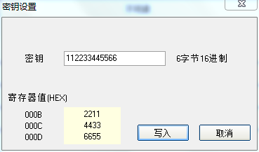
6.Key Register:000B to 000D, You should not only set the block number to operate before you operate the card. Also set the key required to operate the block, this register can be ignored if you select system key authentication at system configuration. if the register key is selected, this register needs to be written.
The key of the card is 6 bytes, stored in 000B to 000D.
For example, card keys:112233445566(Hex), 000B=0x2211,000C=0x4433,000D=0x6655.
Key configuration in the reader demo program:
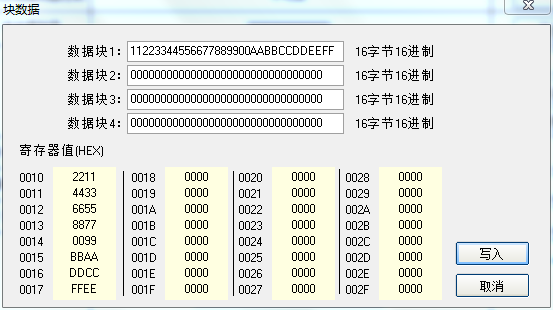
7.Block Data Register:0010 to 002F. There are 32 Registers, can be saved at most 64 bytes. The actual number of registers used with the card operation register.0008 and the data block register to be operated 000A, Minimum bytes of reading and writing of a blocks is16bytes, i.e.8A register.For wallet operation only.4byte, occupation2A register.
For Example writing a block,16 Bytes 11223344556677889900AABBCCDDEEFF,standard 0010 to 0017 registers are as follows:
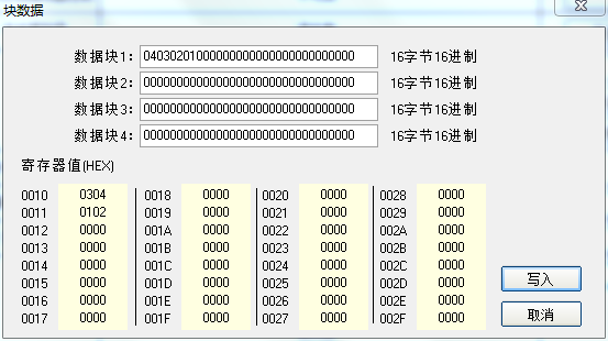
If you operate card wallet value, just write 2 registers. for example 0x01020304 is configured as follows:
Modbus HF reader configuration information introduction.
8.Baud rate and Modbus Station ID, address 40001
Select the corresponding baud rate and station ID to set YW-630 and YW-631, The device's communication baud rate parameter is:Baud rate,No check,8Bit data bit a stop bit. The default station id is 1.
9.System key(the same as key register2,Address is40103,40104,40105)
Modbus ReaderYW-630 and YW-631, there are system key registers that can store card-certified keys, which will continue to be supported. and the setup method has not changed any.
10.Read the card parameter register.
The read card parameter register can set the parameters used for the card operation.
Key type: the type of key used to read and write data blocks,A Key or B Key.
Key mode: can choose two key register authentication, key register.1 Unsaved key for power down, address is.40011,40012,40013。Key registers2A key saved for power - off at the address.40103,40104,40105。
LEDand buzzer:corresponding status prompt after reading the card.
11.Parameter register, address.40100:
Parameter registers can be used for configuration.ModbusWhether to continue to read and write a data block after the reader reads the card, and how the data output of those blocks.
1. Whether reading and writing data skips the key block, the key block must be written according to the corresponding rules, otherwise the current sector will be locked. to avoid this happening, the customer can choose to skip the key block.
2. If the clear card number clears the data area, the clear card system will re-find the card, and if the option is configured, the data area will be cleared at the same time.
3. Data size side mode, as long as PLC display pattern is consistent.
4. If the read card is configured to read and write data blocks, the read and write data blocks are dormant.
5. Read and write block address register, if the card is selected to automatically read the data block, the reader will read the corresponding block data according to this parameter.
6. whether to read the data after finding the card.
12.Read Block Register, Block Register.2 address 40101
If the read block register is configured in the parameter register 2 ,The reader calls the value of the register.
13.Write block register, block register 3, Address 40102
If a write block register is configured in the parameter register 3, The reader calls the value of the register.
14. Key registers 2, address 40103,40104,40105
Key registers 2 is the system key registers, are the same as in the past 6 of bytes, see
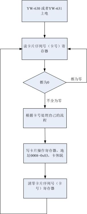
Modbus Reader read IC Tag serial Number:
This is an example that PLC get IC Tag Card serial No.
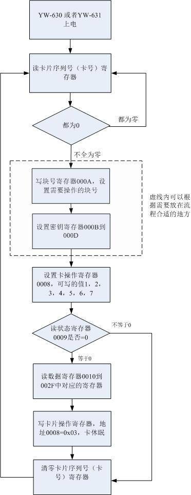
Modbus reader reads the data blocks.:
This is an example that PLC get IC Tag Block Data by modbus reader.
RFID Module, NFC Reader, HF RFID Reader, UHF RFID reader
YOWO RFID (C)2015-2019
Mail:coodor@126.com
QQ:896163157,1403463073

|